1. Prepare circuits
Table of contents
- Prepare “4pin-bus” circuit board
- Prepare WAV Trigger board
- Load the SD card
- Prepare the BNC panel
- Prepare the speaker (optional)
Prepare “4pin-bus” circuit board
Link to OSH Park where the board can be ordered: 4pin-bus
Solder header pins on the “4pin-bus” circuit board, as shown below: 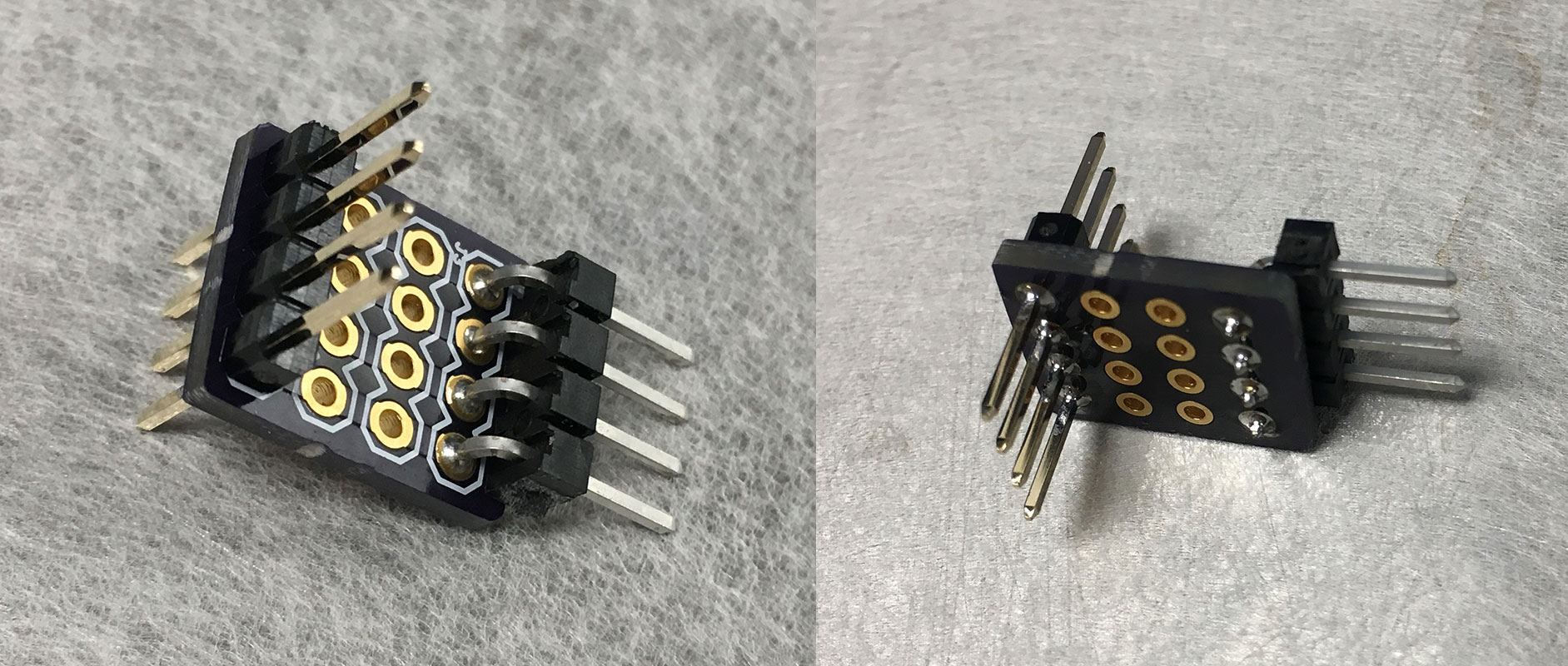
Note that one of the header sets (left one, in above picture) protrudes bidirectionally.
This small circuit board lets us conveniently sample electrical signals (e.g. with Saleae). You can populate the other header slots as well, but the photo shows the minimal number of headers necessary. You can also use right angle headers (as shown) or straight ones.
We need 3 “4-pin bus” circuit boards per active avoidance setup.
Prepare WAV Trigger board
Solder three sets of header pins on the WAV Trigger board, as shown below: 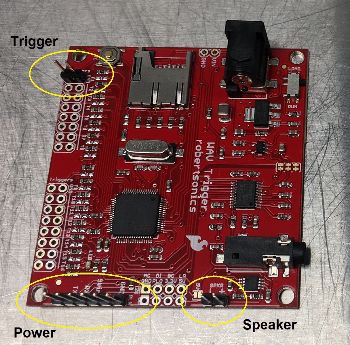
Next, apply a solder jumper to the jumper location indicated by “5V”, as below: 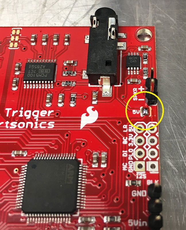
For more information on the jumper, see WAV Trigger user guide
Load the SD card
I use:
Using the above hardware, copy over the two files located here onto the SD card.
The WAV file is the auditory (linear) sweep, from 2 kHz to 6 kHz over 5 seconds. I used this Matlab script to generate the WAV file. While the standard active avoidance protocol uses 4 second trial (and thus CS) periods, I made the WAV file to be 5 seconds long, as to avoid any odd auditory effects at the end of the file.
The INI file provides settings for the WAV Trigger board. (For more info see WAV Trigger user guide.)
After the two files have been loaded onto the SD card, insert the card into the WAV Trigger board until it clicks once.
Make sure that the Load/Run slider switch is in the Run position!
Prepare the BNC panel
Populate the BNC panel as follows: 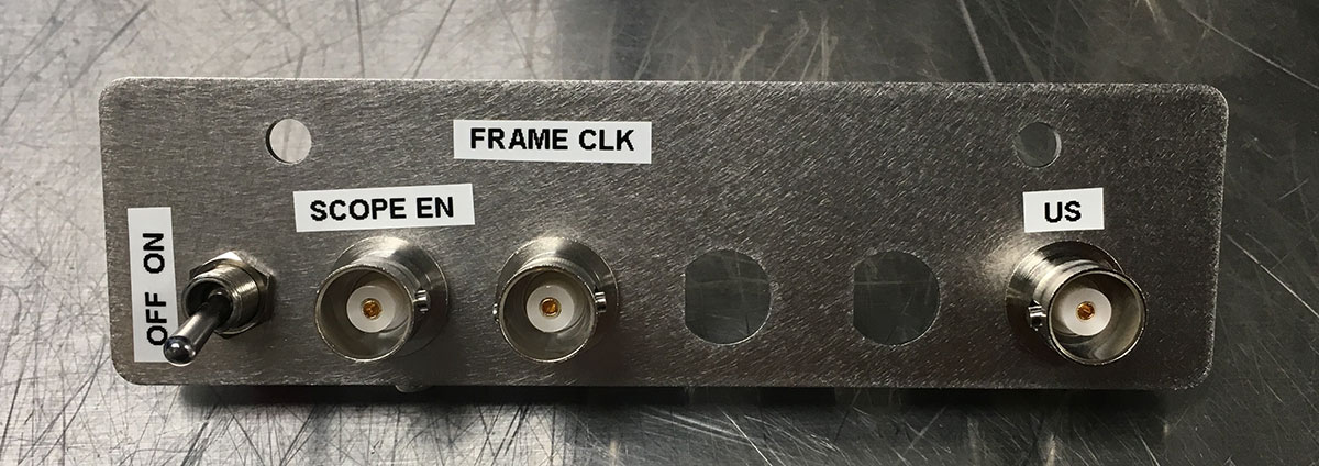
I use the following components from Digikey:
- Toggle switch: EG2350-ND
- Non-isolating BNC bulkhead: ACX1046-ND
Viewed from the back, the components should be wired up as follows: 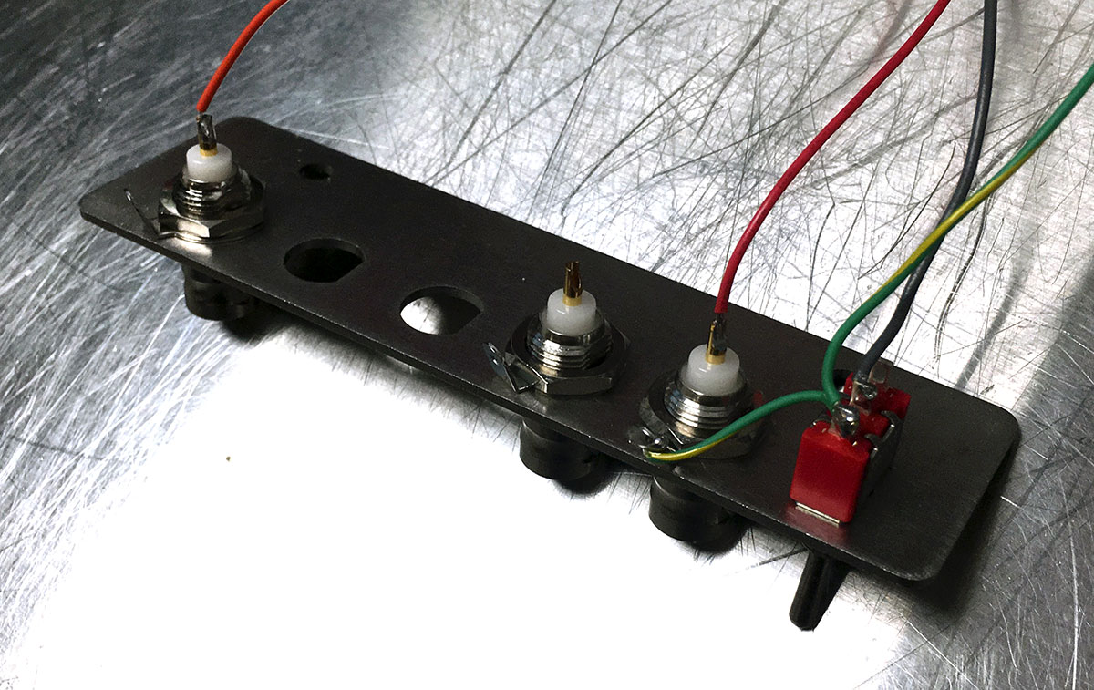
Here, the color code is:
- Green/yellow: Electrical ground
- Gray: Middle pole of the switch
- Red: Scope enable
- Orange: US
We will refer to these colors later in the instructions.
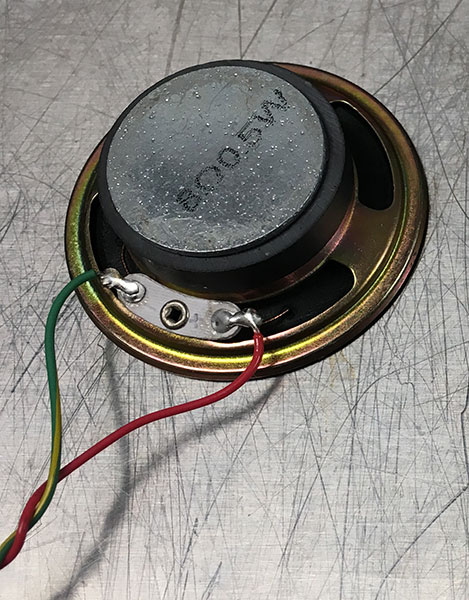
Prepare the speaker (optional)
Solder wires onto a standalone speaker, as shown below: