3. Bottom side of the apparatus
Table of contents
- Initial placement
- Place the 4pin-bus boards on the Arduino
- Wire up the BNC panel
- Wire up the WAV Trigger
- Wire up the encoder
- Wire up Saleae
Initial placement
Place elements on the bottom-side of the apparatus, as shown below. The board shown is the MB8: 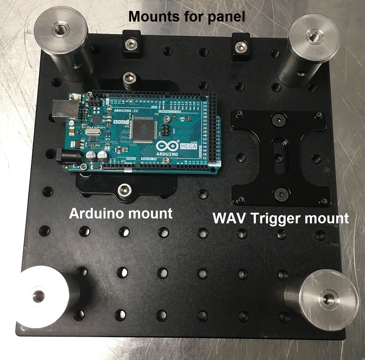 .
.
Some comments:
- For the four legs, I recommend using at least 2 inch tall posts (e.g. RS2P).
- The WAV Trigger mount needs to be screwed on with “low-profile” (i.e. smaller head) #1/4”-20 screws, for example 92220A182 from McMaster-Carr.
- The panel mounts also need low-profile screws, but longer lengths. For example: 92220A185 from McMaster-Carr. (I recommend stocking multiple lengths.)
Next, mount the WAV Trigger board using #4-40 screws as follows. In the picture, I also mounted the three “4pin-bus” circuit boards on the Arduino: 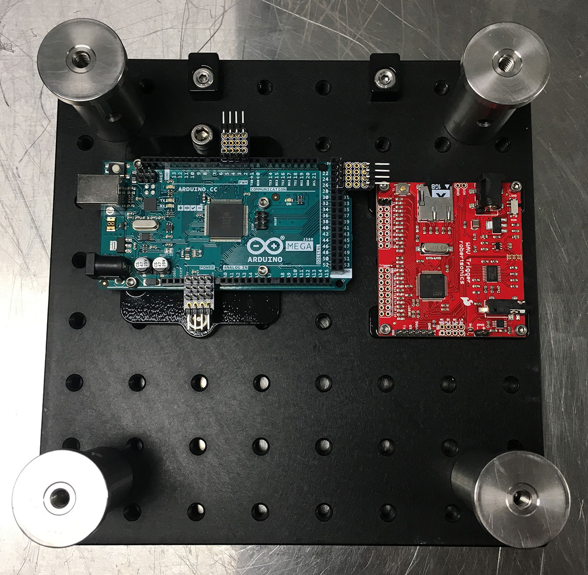 .
.
Place the 4pin-bus boards on the Arduino
Here are more detailed photographs showing the placement of the three “4pin-bus” circuit boards.
First “4pin-bus” board goes on pins 2, 3, 4, 5 of the Arduino: 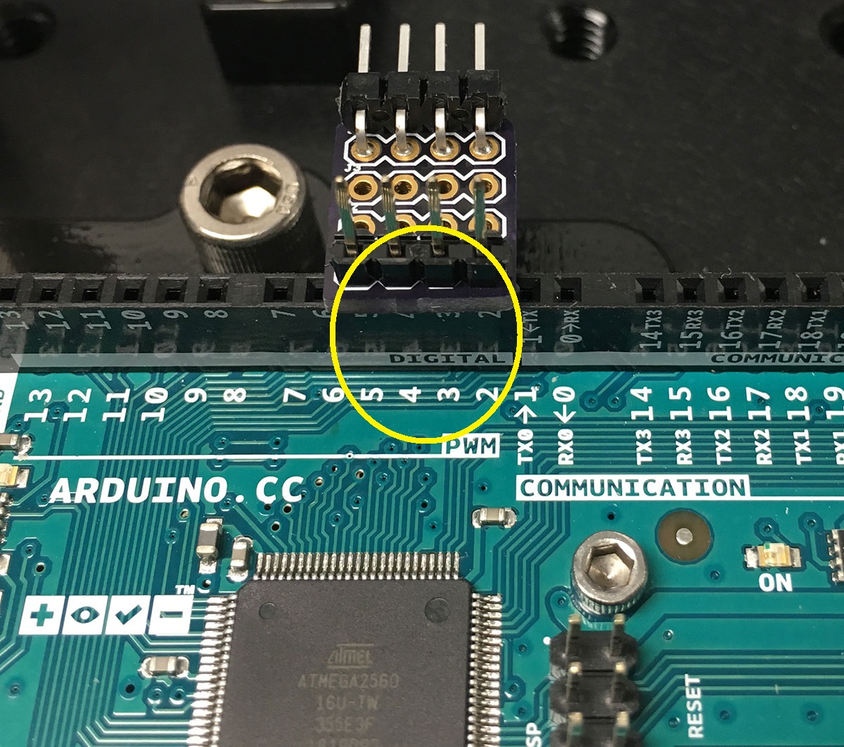
The second “4pin-bus” board goes on pins 23, 25, 27, 29 of the Arduino: 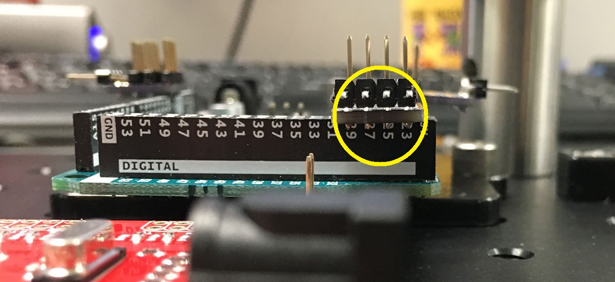
The final “4pin-bus” board goes on 5V, GND, GND, Vin pins of the Arduino: 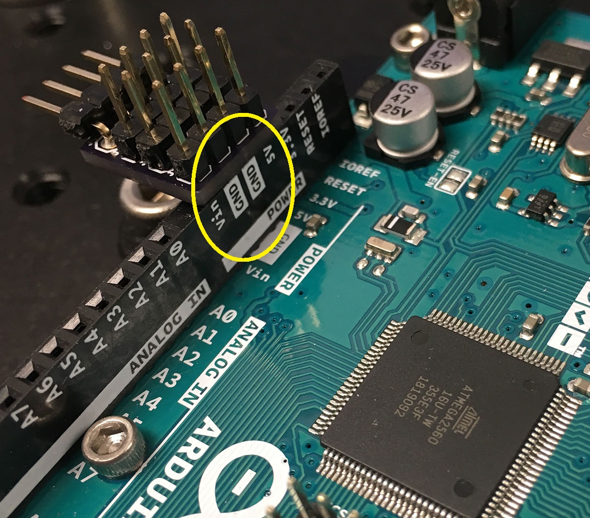
Wire up the BNC panel
First, mount the populated BNC panel onto the board using #8-32 screws on the adapters: 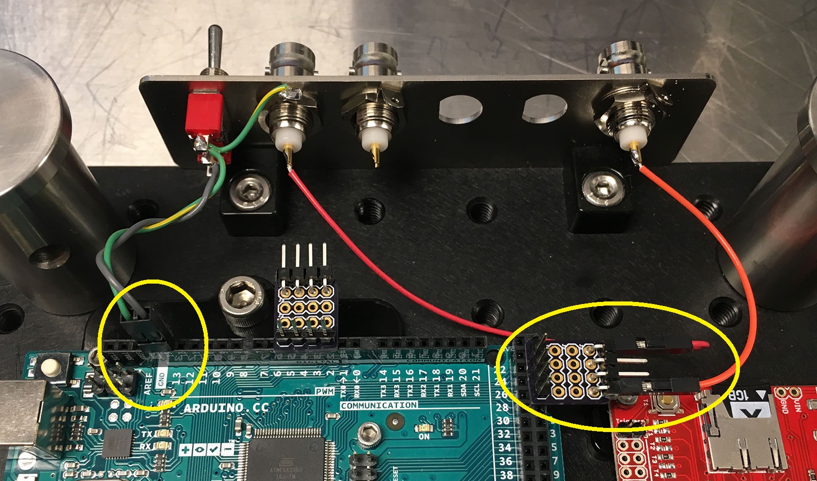
I use a 2x1 male header pin to connect the gray wire (center pole of the switch) to pin 13 of the Arduino, and the green/yellow wire (panel ground) to the adjacent GND pin of the Arduino.
I use a 1x1 female header socket to connect the red wire (scope enable) to pin 23 of the Arduino. Similarly, the orange wire (US) is connected to pin 29 of the Arduino.
Wire up the WAV Trigger
We first need to provide power to the WAV Trigger board. From the Arduino board, I tapped off 5V (red wire) and GND (green/yellow wire) and routed it to the power input pins of the WAV Trigger board: 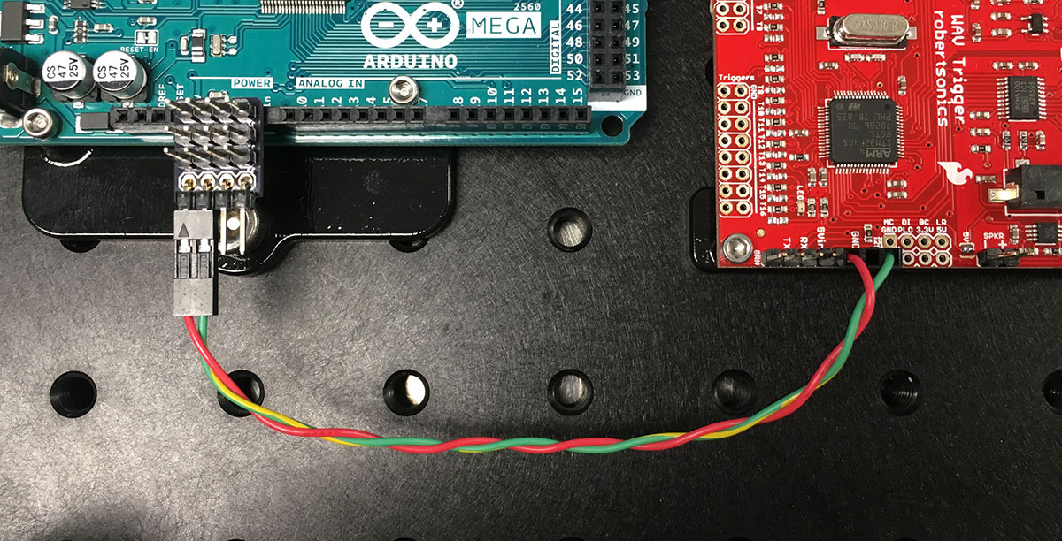
Next, I connected pin 27 of the Arduino (“CS” signal) to the trigger input (“T1”) of the WAV Trigger board. In the photo below, this connection is made with a blue wire: 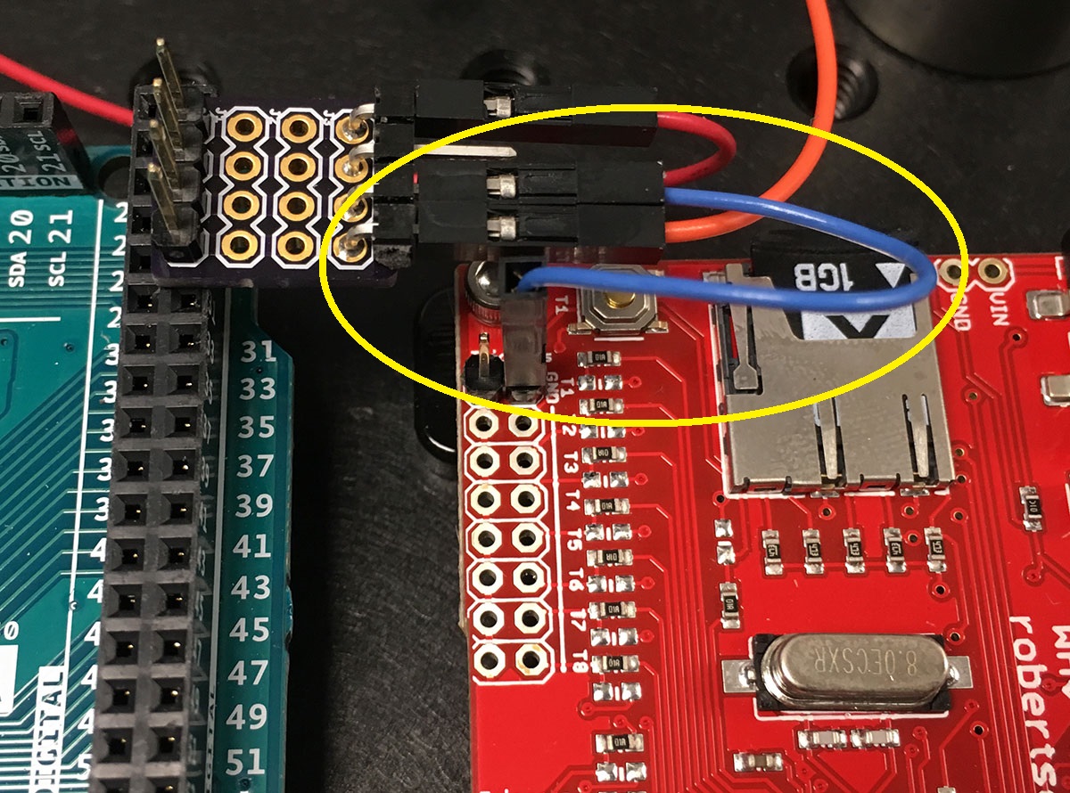
Finally, if you are planning on using an OEM speaker module, you can connect that to the WAV Trigger board as shown below: 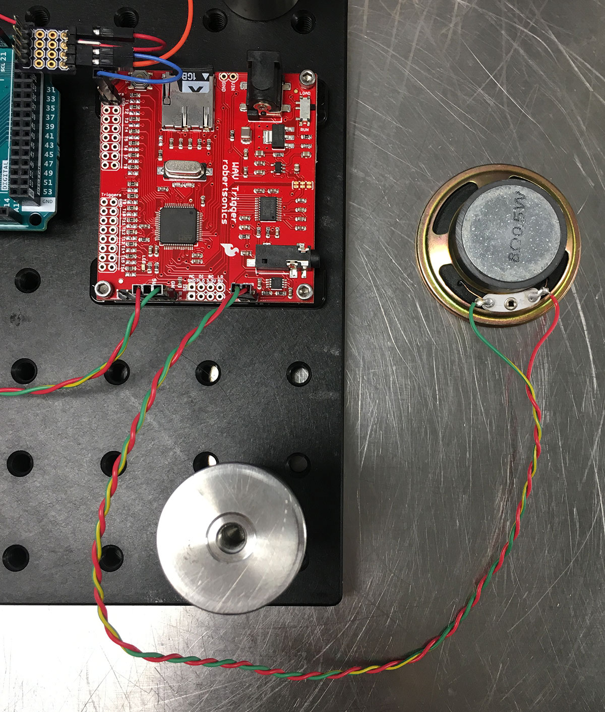
Wire up the encoder
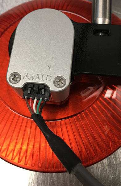
The pinout for the HB5M encoder can be seen on the bottom side of the device. Signals “A”, “B”, and “I” are encoder readouts, whereas “5V” and “GND” are power lines:
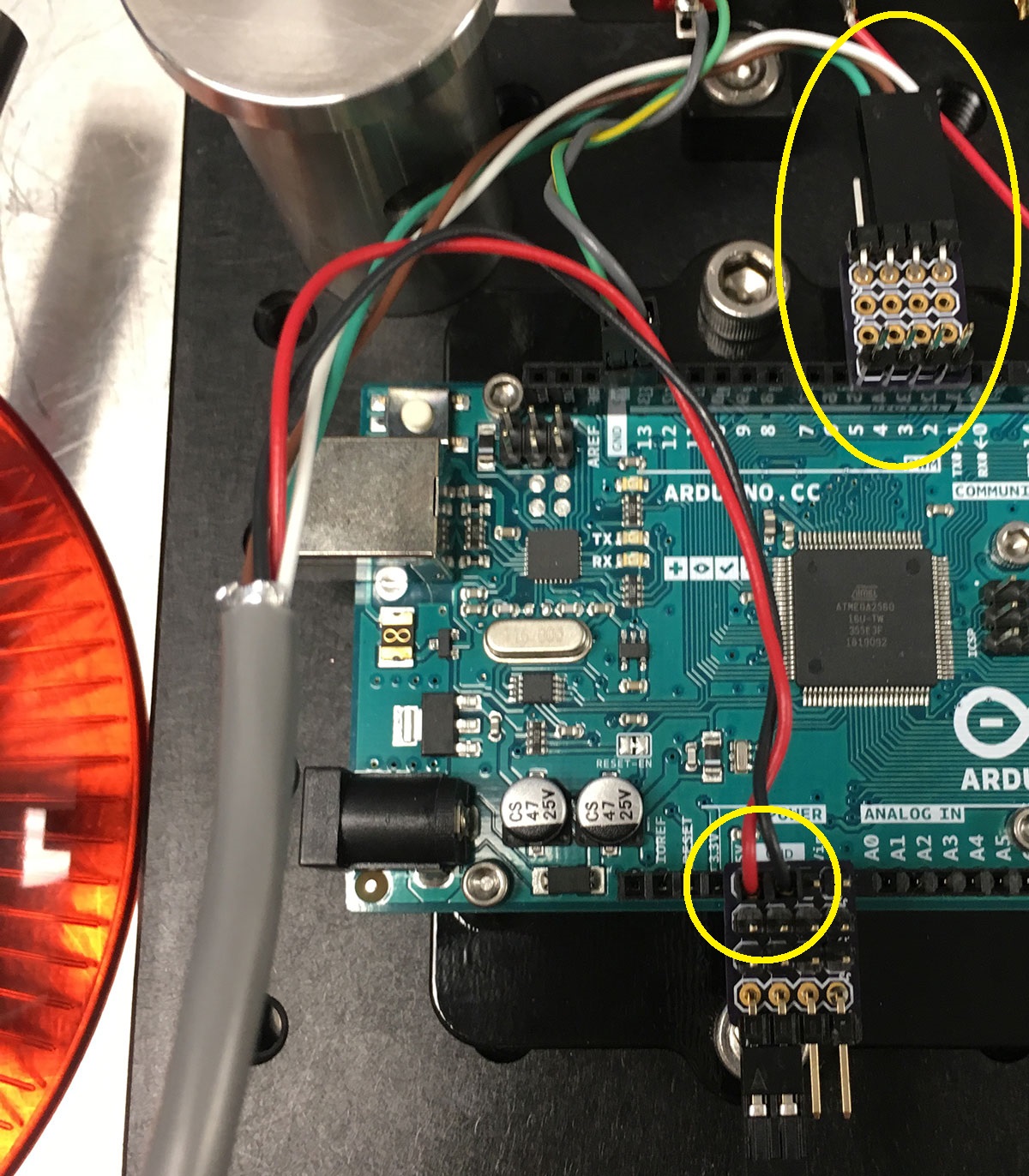
On the Arduino side, the encoder power wires (red and black) are routed to the “5V” and “GND” pins of the Arduino. As for the encoder signals:
- Encoder A (white) is routed to Arduino pin 2,
- Encoder B (brown) is routed to Arduino pin 3,
- Encoder I (green) is routed to Arduino pin 4.
Wire up Saleae
Position the Saleae as shown below. I use double sided tape (the “Nitto” tape works particularly well) to secure the Saleae to the platform: 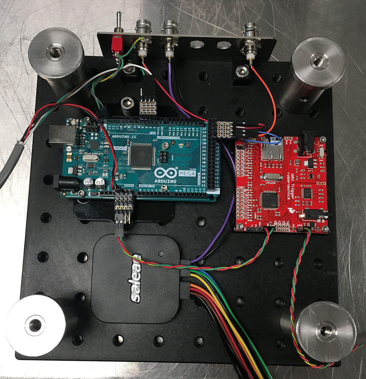
Next, directly solder Channel 7 of Saleae (purple wire; note that Saleae channel index starts from 0) and its associated ground wire to the BNC port labeled “Frame clock”. 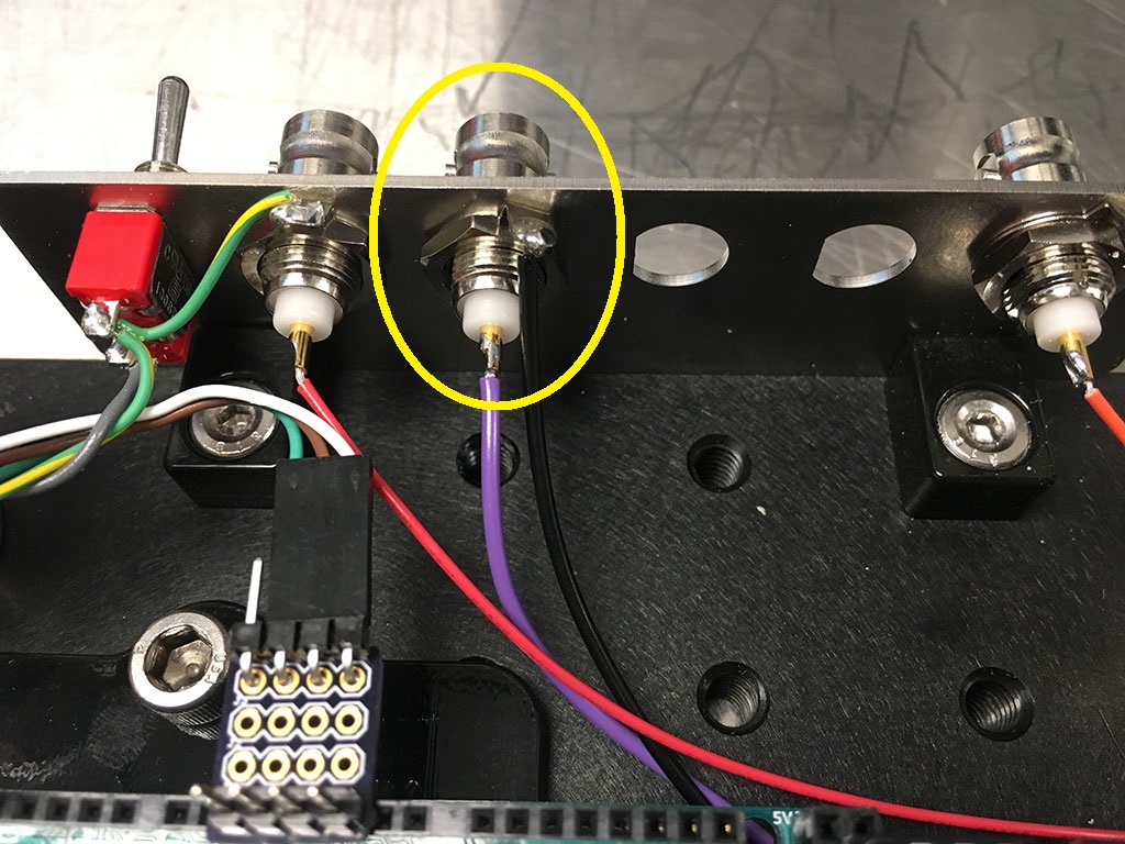
Then connect the remaining channels of Saleae according to the following table:
| Saleae | Arduino | Function |
|---|---|---|
| Ch0 (black) | Pin 2 | Encoder A |
| Ch1 (brown) | Pin 3 | Encoder B |
| Ch2 (red) | Pin 4 | Encoder I |
| Ch3 (orange) | Pin 23 | Scope enable |
| Ch4 (yellow) | Pin 25 | Trial clock |
| Ch5 (green) | Pin 27 | CS |
| Ch6 (blue) | Pin 29 | US |
The ground wires of the Saleae are redundant. However, I like to take at least two of the Saleae ground wires (any two) and connect them to the ground pins of the Arduino as shown below: 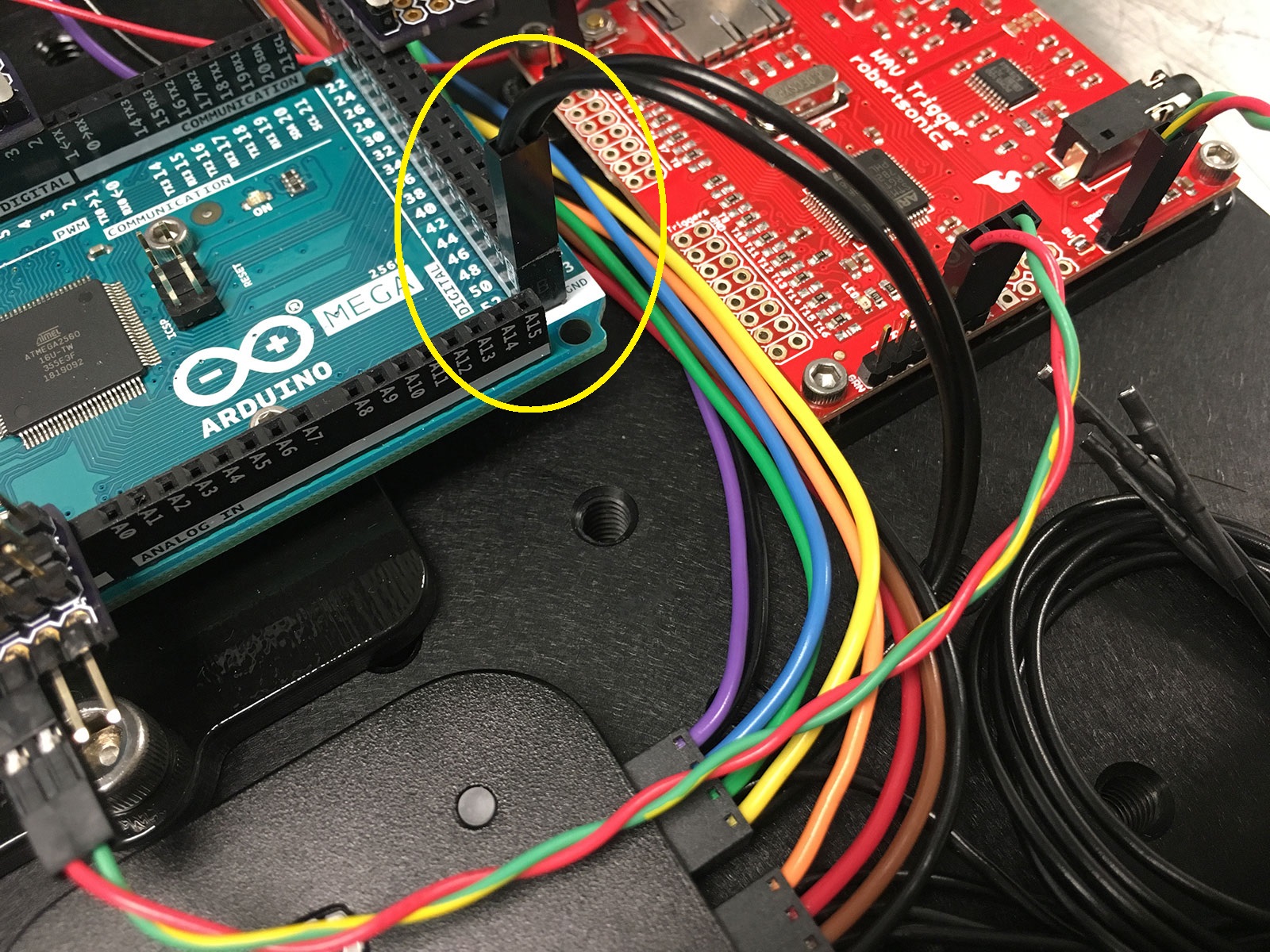
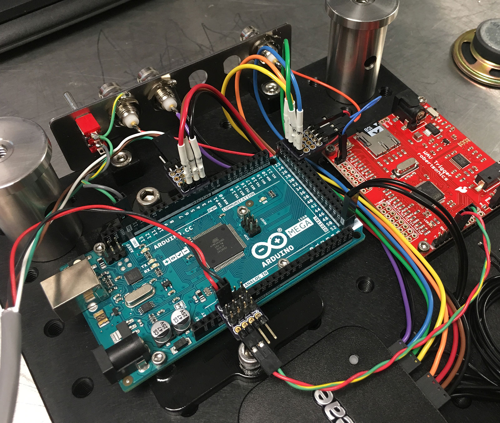
The complete Saleae wiring should look like as follows: